Goal of this week is Add an output device to a micro controller board you've designed and program it to do something
First, I start to study about several output devices for connecting with my microcontroller board. An output device is any device used to send data from a electrical circuit/ computer to another device or user
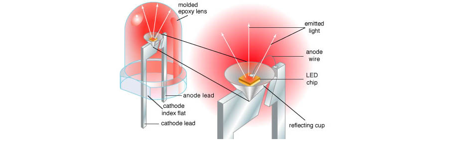
Light-emitting diode (LED)
A light-emitting diode (LED) is a two-lead semiconductor light source. It is a p-n junction diode, which emits light when activated. When a suitable voltage is applied to the leads, electrons are able to recombine with electron holes within the device, releasing energy in the form of photons. This effect is called electroluminescence, and the color of the light (corresponding to the energy of the photon) is determined by the energy band gap of the semiconductor
>
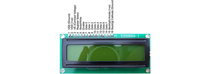
Liquid-crystal display (LCD)
A liquid-crystal display (LCD) is a flat-panel display or other electronic visual display that uses the light-modulating properties of liquid crystals. Liquid crystals do not emit light directly.
LCDs are available to display arbitrary images (as in a general-purpose computer display) or fixed images with low information content, which can be displayed or hidden, such as preset words, digits, and 7-segment displays as in a digital clock. They use the same basic technology, except that arbitrary images are made up of a large number of small pixels, while other displays have larger elements
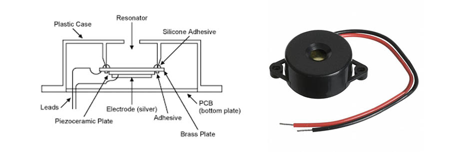
Piezo Buzzer
Piezo buzzer is an electronic out put device commonly used to produce sound. Light weight, simple construction and low price make it usable in various applications like car/truck reversing indicator, computers, call bells etc .Piezo buzzer is based on the inverse principle of piezo electricity discovered in 1880 by Jacques and Pierre Curie. It is the phenomena of generating electricity when mechanical pressure is applied to certain materials and the vice versa is also true. Such materials are called piezo electric materials
Speaker
A loudspeaker (or loud-speaker or speaker) is an electroacoustic transducer; which converts an electrical audio signal into a corresponding sound.
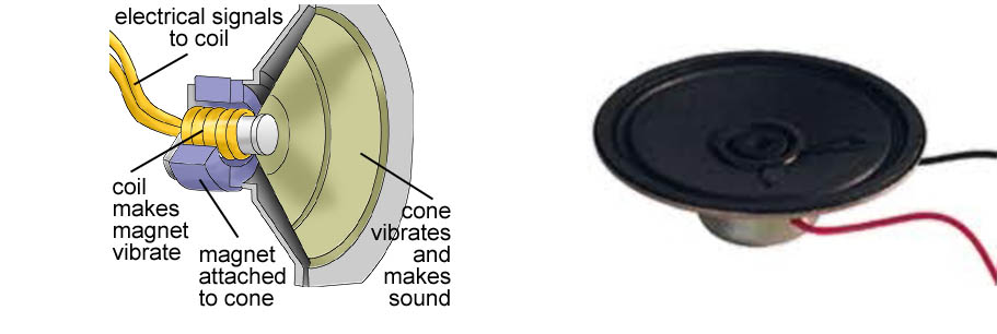
The most widely used type of speaker today is the dynamic speaker, invented in 1925 by Edward W. Kellogg and Chester W. Rice. The dynamic speaker operates on the same basic principle as a dynamic microphone, but in reverse, to produce sound from an electrical signal. When an alternating current electrical audio signal is applied to its voice coil, a coil of wire suspended in a circular gap between the poles of a permanent magnet, the coil is forced to move rapidly back and forth due to Faraday's law of induction, which causes a diaphragm (usually conically shaped) attached to the coil to move back and forth, pushing on the air to create sound waves. Besides this most common method,
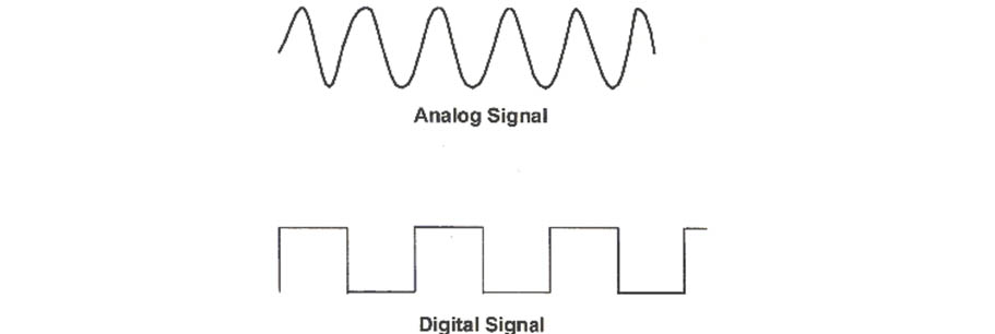
An analog or analogue signal is any continuous signal for which the time varying feature (variable) of the signal is a representation of some other time varying quantity,.
A digital signal refers to an electrical signal that is converted into a pattern of bits. Unlike an analog signal, which is a continuous signal that contains time-varying quantities, a digital signal has a discrete value at each sampling point.
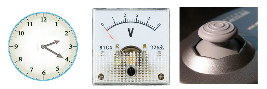
Analog device is usually a combination of both analog machine and analog media that can together measure, record, reproduce, or broadcast continuous information, for example, the almost infinite number of grades of transparency, voltage, resistance, rotation, or pressure
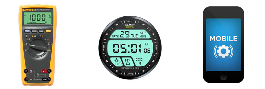
A digital device is an electronic device which uses discrete, numerable data and processes for all its operations. The alternative type of device is analog, which uses continuous data and processes for any operations. Any device which uses a computer of any sort in its operations is at least partially digital.
Then I star to design my microcontroller board with a speaker
Design the board
software: Eagle
First part of this weeks' assignment was design the board on eagle software. This week I also came across some very useful tutorials on board layout design in Eagle .
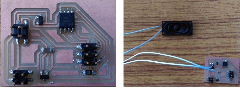
I try to make neils example hello.speaker.45 board with a speaker to see which tones I can generate with a simple circuit
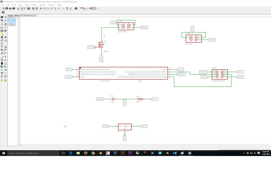
The designed a board allows a 12V or 9V power supply to connect to the speaker and a 5V regulator that provides VCC to the rest of the board. Then a MOSFET, a 4 pin header for programing the micro controller ,1k resistor and 1uf capacitor
In the boar used a MOSFE. The MOSFET is metal-oxide-semiconductor field-effect transistor (MOSFET, MOS-FET, or MOS FET), a type of transistor used for amplifying or switching electronic signals.
Download Eagle file from here
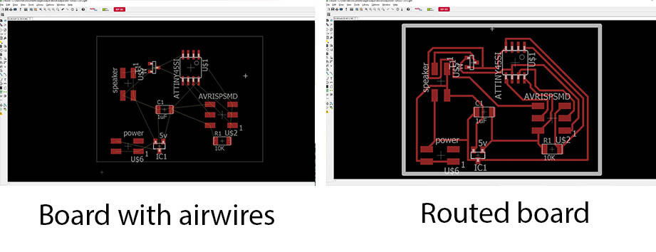
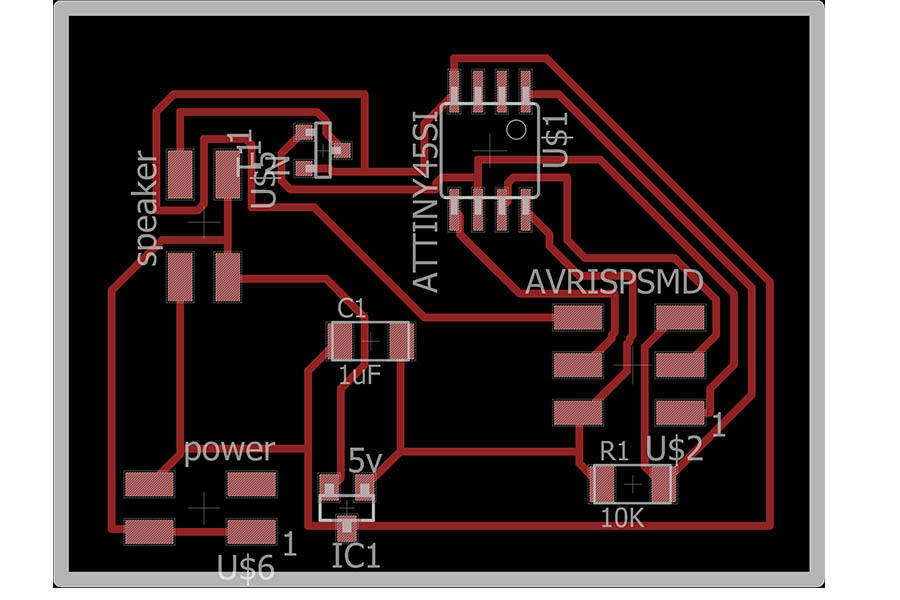
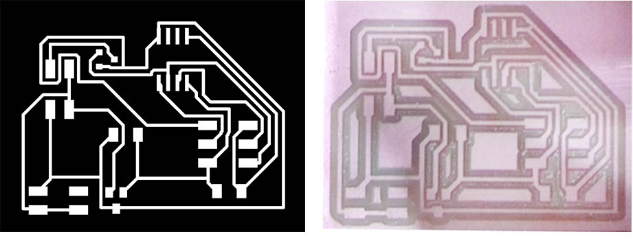
Milling the board
Macine: roland mdx-20 (modela )
Download file to mill from here
Stuffing the board
Components I used for the board
The designed a board allows a 12V or 9V power supply to connect to the speaker and a 5V regulator that provides VCC to the rest of the board.
5V voltage regulator .In this boar I am using LM3480IM3-5
Then a n- channel MOSFET, for amplifying microcontroller PWM signal
The MOSFET is metal-oxide-semiconductor field-effect transistor (MOSFET, MOS-FET, or MOS FET), a type of transistor used for amplifying or switching electronic signals.
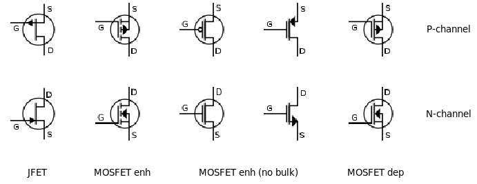
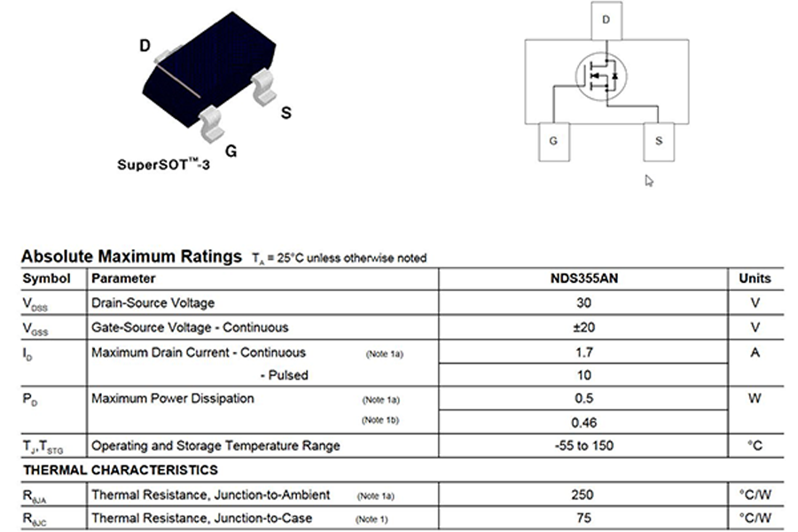
In this boar I am using NDS355AN MOSFET
a 4 pin header for programing the micro controller ,1k resistor and 1uf capacitor
Programming the board
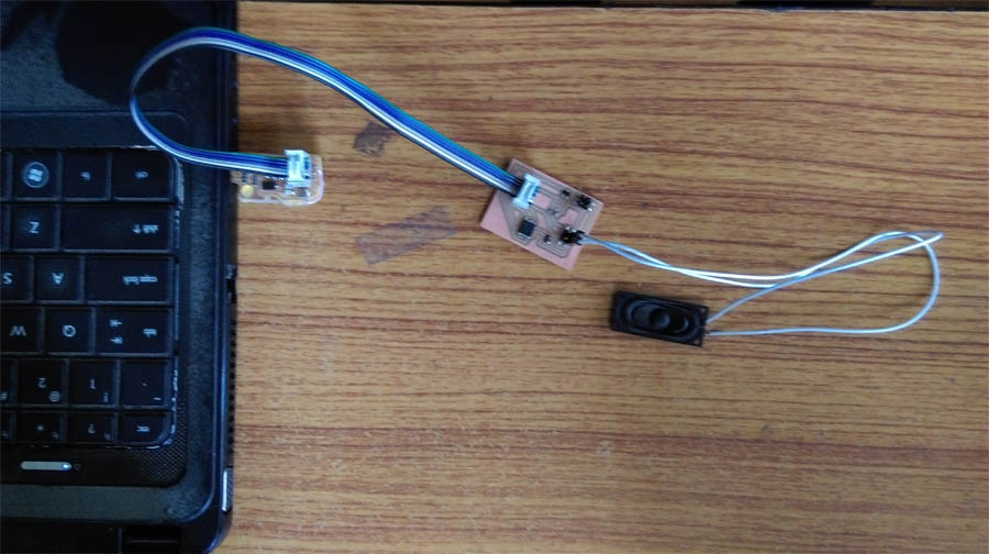
Programming the board using Arduino IDE. I intended to serial connect this board using the ISP connection.
The board was then connected to the programmer isp board/computer then burn program to micro controller .
The main sketch for Arduino speaker is as follows
#include"pitches.h"


int melody[] = {
  NOTE_D4, NOTE_G4, NOTE_FS4, NOTE_A4,
  NOTE_G4, NOTE_C5, NOTE_AS4, NOTE_A4,
  NOTE_FS4, NOTE_G4, NOTE_A4, NOTE_FS4, NOTE_DS4, NOTE_D4,
  NOTE_C4, NOTE_D4,0,

  NOTE_D4, NOTE_G4, NOTE_FS4, NOTE_A4,
  NOTE_G4, NOTE_C5, NOTE_D5, NOTE_C5, NOTE_AS4, NOTE_C5, NOTE_AS4, NOTE_A4,      //29               //8
  NOTE_FS4, NOTE_G4, NOTE_A4, NOTE_FS4, NOTE_DS4, NOTE_D4,
  NOTE_C4, NOTE_D4,0,

  NOTE_D4, NOTE_FS4, NOTE_G4, NOTE_A4, NOTE_DS5, NOTE_D5,
  NOTE_C5, NOTE_AS4, NOTE_A4, NOTE_C5,
  NOTE_C4, NOTE_D4, NOTE_DS4, NOTE_FS4, NOTE_D5, NOTE_C5,
  NOTE_AS4, NOTE_A4, NOTE_C5, NOTE_AS4,             //58

  NOTE_D4, NOTE_FS4, NOTE_G4, NOTE_A4, NOTE_DS5, NOTE_D5,
  NOTE_C5, NOTE_D5, NOTE_C5, NOTE_AS4, NOTE_C5, NOTE_AS4, NOTE_A4, NOTE_C5, NOTE_G4,
  NOTE_A4, 0, NOTE_AS4, NOTE_A4, 0, NOTE_G4,
  NOTE_G4, NOTE_A4, NOTE_G4, NOTE_FS4, 0,

  NOTE_C4, NOTE_D4, NOTE_G4, NOTE_FS4, NOTE_DS4,
  NOTE_C4, NOTE_D4, 0,
  NOTE_C4, NOTE_D4, NOTE_G4, NOTE_FS4, NOTE_DS4,
  NOTE_C4, NOTE_D4, END

};

// note durations: 8 = quarter note, 4 = 8th note, etc.
int noteDurations[] = {       //duration of the notes
  8,4,8,4,
  4,4,4,12,
  4,4,4,4,4,4,
  4,16,4,

  8,4,8,4,
  4,2,1,1,2,1,1,12,
  4,4,4,4,4,4,
  4,16,4,

  4,4,4,4,4,4,
  4,4,4,12,
  4,4,4,4,4,4,
  4,4,4,12,

  4,4,4,4,4,4,
  2,1,1,2,1,1,4,8,4,
  2,6,4,2,6,4,
  2,1,1,16,4,

  4,8,4,4,4,
  4,16,4,
  4,8,4,4,4,
  4,20,
};

int speed=90;  //higher value, slower notes
void setup() {

  Serial.begin(9600);
  for (int thisNote = 0; melody[thisNote]!=-1; thisNote++) {

    int noteDuration = speed*noteDurations[thisNote];
    tone(3, melody[thisNote],noteDuration*.95);
    Serial.println(melody[thisNote]);

    delay(noteDuration);

    noTone(3);
  }
}

void loop() {
  // no need to repeat the melody.
}#define NOTE_B0 31
#define NOTE_C1 33
#define NOTE_CS1 35
#define NOTE_D1 37
#define NOTE_DS1 39
#define NOTE_E1 41
#define NOTE_F1 44
#define NOTE_FS1 46
#define NOTE_G1 49
#define NOTE_GS1 52
#define NOTE_A1 55
#define NOTE_AS1 58
#define NOTE_B1 62
#define NOTE_C2 65
#define NOTE_CS2 69
#define NOTE_D2 73
#define NOTE_DS2 78
#define NOTE_E2 82
#define NOTE_F2 87
#define NOTE_FS2 93
#define NOTE_G2 98
#define NOTE_GS2 104
#define NOTE_A2 110
#define NOTE_AS2 117
#define NOTE_B2 123
#define NOTE_C3 131
#define NOTE_CS3 139
#define NOTE_D3 147
#define NOTE_DS3 156
#define NOTE_E3 165
#define NOTE_F3 175
#define NOTE_FS3 185
#define NOTE_G3 196
#define NOTE_GS3 208
#define NOTE_A3 220
#define NOTE_AS3 233
#define NOTE_B3 247
#define NOTE_C4 262
#define NOTE_CS4 277
#define NOTE_D4 294
#define NOTE_DS4 311
#define NOTE_E4 330
#define NOTE_F4 349
#define NOTE_FS4 370
#define NOTE_G4 392
#define NOTE_GS4 415
#define NOTE_A4 440
#define NOTE_AS4 466
#define NOTE_B4 494
#define NOTE_C5 523
#define NOTE_CS5 554
#define NOTE_D5 587
#define NOTE_DS5 622
#define NOTE_E5 659
#define NOTE_F5 698
#define NOTE_FS5 740
#define NOTE_G5 784
#define NOTE_GS5 831
#define NOTE_A5 880
#define NOTE_AS5 932
#define NOTE_B5 988
#define NOTE_C6 1047
#define NOTE_CS6 1109
#define NOTE_D6 1175
#define NOTE_DS6 1245
#define NOTE_E6 1319
#define NOTE_F6 1397
#define NOTE_FS6 1480
#define NOTE_G6 1568
#define NOTE_GS6 1661
#define NOTE_A6 1760
#define NOTE_AS6 1865
#define NOTE_B6 1976
#define NOTE_C7 2093
#define NOTE_CS7 2217
#define NOTE_D7 2349
#define NOTE_DS7 2489
#define NOTE_E7 2637
#define NOTE_F7 2794
#define NOTE_FS7 2960
#define NOTE_G7 3136
#define NOTE_GS7 3322
#define NOTE_A7 3520
#define NOTE_AS7 3729
#define NOTE_B7 3951
#define NOTE_C8 4186
#define NOTE_CS8 4435
#define NOTE_D8 4699
#define NOTE_DS8 4978
#define END -1